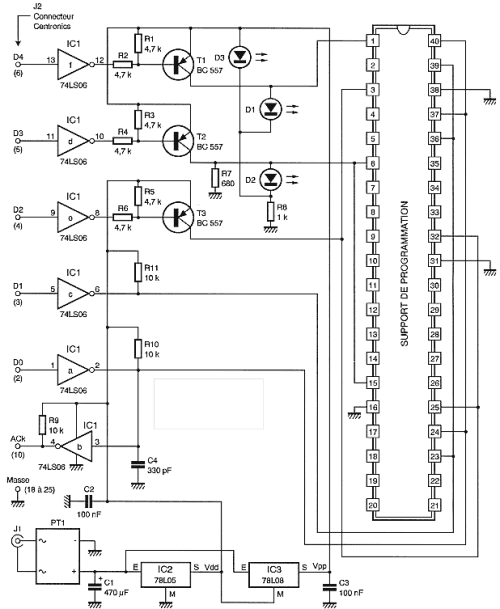
PIC Universal Programmer Schematic

The signals from a parallel port is standard TTL and being "abused" by their journey on the cable connections, they are reshaped by inverters contained in IC1. As this circuit has open collector outputs it allows easy control of three transistors T1, T2 and T3. T1 and T2 allow the application of high programming voltage VPP legs adequate support universal programmer. T3 controls the normal supply voltage VDD applied also to the universal support.
This can only supply circuit to program only when really necessary and thus avoid any problems during its insertion or extraction of its programming support. Two red LEDs, D1 and D2 indicate the presence of tension on the support. D3 for its light just when the timer is turned to signal the proper functioning of the food.
Data to be programmed by IC1A pass while they go through IC1b at a replay of the circuit. The clock programming through IC1c. Support for receiving circuits to program is a model 40 feet a bit special so they can receive the PIC cases: 8, 18, 20, 28 and 40 feet. The wiring of different supplies, the data line and clock line is made in accordance with the pinouts of the various circuits.
The feeding program is simple but very tolerant. Two stabilized voltages are required: 5 volts to 13 volts and VDD for programming voltage VPP. IC2 is a 78L05 loads of 5 volts while IC3, which is a 78L08, produces 13 volts because it is not referenced to ground but the output of IC2 and product and 5 + 8 or 13 volts! To accept any external source, regulators are preceded by a generous filter and bridge rectifier. You can apply any J1 AC voltage between 12 volts and 20 or between 16 and 30 volts. The flow required is only about 100 mA.